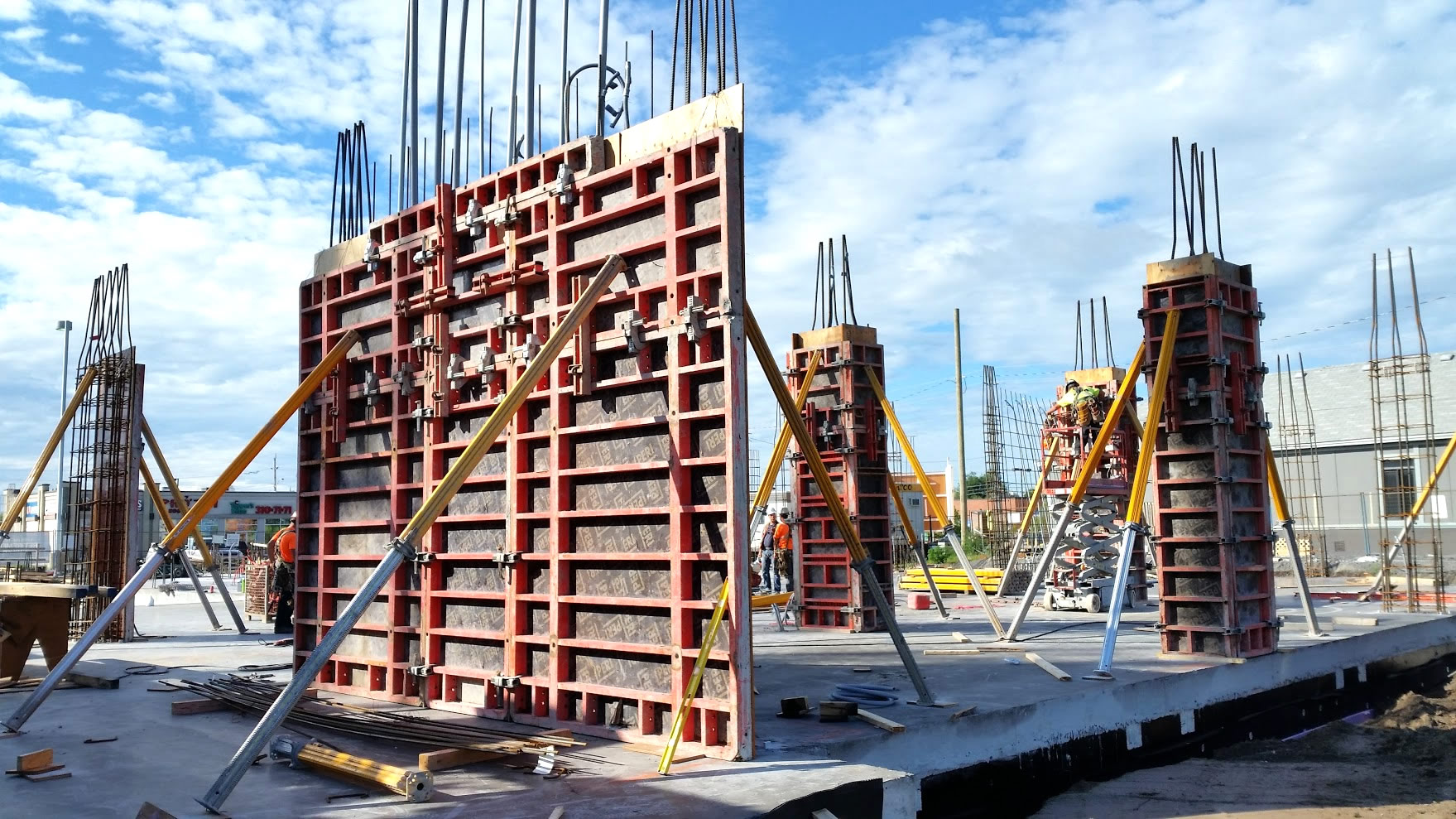
Concrete maturity is a crucial metric in the construction industry, providing insights into the strength and readiness of concrete for critical operations (i.e. stripping forms, stressing cables, etc.) The installation of sensors in concrete samples for maturity calibration is a technical process that varies depending on the region and the type of concrete sample used. In this blog, we will explore the differences in sensor installation procedures for 4×8-inch cylinders, 6×12-inch cylinders, and concrete cubes.
Explore 12 Futuristic Technology Trends Solving Concrete's Biggest Challenges.
Learn all you need to know about maturity-based concrete strength monitoring here!
Understanding Concrete Maturity
Before delving into the installation process, it’s important to understand what concrete maturity is. It is a measure of how much a concrete mix has cured over time, factoring in the temperature history of the concrete. This is crucial because the strength of concrete is directly related to its maturity index which is typically a unit of degree hours or equivalent days.
Sensor Installation in Concrete Samples
1. 4×8 Inch Cylinders (Canada vs. US)
In Canada, 4×8-inch cylinders are filled in three layers, and each layer is rodded 25 times using a standard tamping rod. Sensors are typically inserted after the second layer is rodded. Contractors should approach the sensor placement with care at the center of the cylinder, both vertically and horizontally, to accurately measure the temperature throughout the curing process.
In contrast, the USA method involves filling the cylinder in two layers. Each layer is rodded 25 times with a standard tamping rod. Unlike the Canadian method, contractors can place the sensor after rodding the first layer. Placement is critical for accurate readings and should be at the mid-height and mid-radius of the cylinder.
2. 6×12 Inch Cylinders
These larger samples follow a similar layering and tamping/rodding process as the 4×8-inch cylinders but require more material per layer. Due to their size, it is vital to ensure that contractors place the sensor at the geometric center of the 6×12-inch cylinder. The larger volume can lead to more significant temperature gradients, making accurate sensor placement even more crucial.
3. Concrete Cubes (6in x 6in x 6in)
Common in regions outside North America, concrete cubes are cast in steel or cast-iron moulds. The moulds are filled in 3 layers and are compacted 35 times per layer with a standard tamping rod. Sensors in cubes are typically placed after the cube is half-filled. The placement of the sensor should be central both in terms of height and the plan area of the cube.
In all the cases described above, the recommendation is to avoid rodding the last layer of concrete. Instead, using a rubber mallet one can consolidate the last layer to prevent pushing the sensor to the inner portion of the sample. This ensures that the measurement location remains central, capturing the hydration heat of the concrete sample for accurate maturity calibration purposes.
Incorporating Giatec’s SmartRock for Various Installation Techniques
SmartRock® is an advanced concrete sensor that offers versatility for different installation techniques. To use it, users must remember to activate the sensor before installation. Here’s how to use it for three specific installation methods:
One sensor in One Cylinder
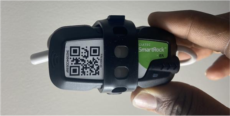
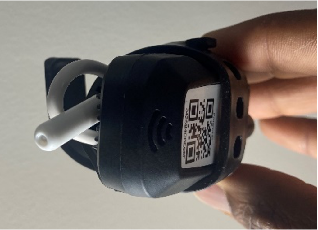
1. Body + Temperature Probe:
Before placing the sensor in the cylinder, the temperature probe + body must be secured as one unit with the help of the installation strap. The sensor can now be placed in the geometric center of the concrete cylinder or cube.
2. Temperature Probe Only:
The temperature probe can be inserted into the concrete cylinder after the second layer has been placed. Contractors must ensure to place it at the mid-height of the cylinder for representative temperature profiling. The same principle applies to cubes as well.
One Sensor in Two Cylinders
3. Temperature Probe and Body in Two Respective Cylinders:
Overall, this method involves using one SmartRock sensor to monitor two cylinders simultaneously. The body is placed in one cylinder and the temperature probe in the other. This technique requires precise coordination to ensure that both components of the sensor are correctly positioned in their respective cylinders for accurate data collection. Additionally, it is imperative to secure both samples together through tape or other means. This will help avoid cable damage while transporting the samples from the initial to the final curing location (job site to the lab).
Considerations for Sensor Installation
- Accuracy:
- Contractors must accurately place the sensor at the center of the sample for precise readings.
- Secure Placement:
- Contractors must firmly secure the sensor to prevent displacement during the filling and compaction process.
Conclusion
The installation of sensors in concrete samples for maturity calibration is a nuanced process that varies based on regional practices and the dimensions of the concrete sample. Understanding these differences is vital for engineers and construction professionals to ensure accurate and reliable maturity readings. In sum, this knowledge not only contributes to the structural integrity of concrete constructions but also aids in the efficient management of curing time and resources.
References
- ASTM International. (2019). Standard Practice for Estimating Concrete Strength by the Maturity Method (ASTM C1074). ASTM International.
- ASTM International. (2019). Standard Practice for Making and Curing Concrete Test Specimens in the Field (ASTM C31/C31M-19). ASTM International.
- British Standards Institution. (2019). Testing hardened concrete – Part 2: Making and curing specimens for strength tests (BS EN 12390-2). BSI Standards Limited.

